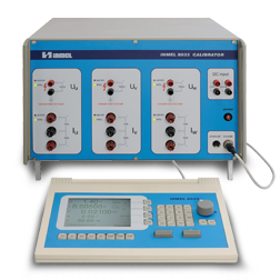
INMEL 8033/8031
The calibrator INMEL 8033 is the power and energy calibrator in the three-phase system producing on six outputs three voltage courses and three current courses. These courses are shifted in relation to themselves for given phase angle.
A discriminant this calibrator is the digital method of the generation, the measurement and the stabilization of parameters of output signals. The generation of signals in voltage and current tracks one realized based on integrated circuit of the direct digital synthesis of the frequency (DDS). To the realization of the feedback loop one applied the precise digital multitransducer realized on the basis of the high grade of transducers A/C and the processor of DSP signal. Accepted solution makes possible generating of courses deformed to 25-this of harmonic and assure the large stability of amplitudes, frequencies and phases of generated signals.
Calibrator versions
Calibrator's performance is highly enhanced by a set of additional functions, which simplify the measurements.
Increase or decrease value of output quantity with value by hand wheel – for quantity: U, I,*, f, cos*, P, Q.
Error calculation of checked watt-hour meter after setting the number of disc revolutions (impulse).
Generate energy portions set.
Disconnection and connection auto range change for voltage and currents outputs with transitions:
140 140.001V,
280 280.001V,
0.5 0.500001A,
2.5 2.50001A,
10 10.00001 A.
Independent switch on and switch off tracks CH(U), CH(V), CH(W) voltage and
current, only voltage, only current
Choose local/remote control by interface RS 232, IEEE 488.
Simultaneous switch on/switch off all outputs by OPERATE, STANDBY keys.
Choose three phase, two phase single phase set.
Setup parameters of harmonic courses put on course voltage and current.
Work in three-phase asymmetric set.
Possibility to synchronize the output course of calibrator with supply frequency
Possibility current generation up to 300A with parallel conection the current blocks.
A discriminant this calibrator is the digital method of the generation, the measurement and the stabilization of parameters of output signals. The generation of signals in voltage and current tracks one realized based on integrated circuit of the direct digital synthesis of the frequency (DDS). To the realization of the feedback loop one applied the precise digital multitransducer realized on the basis of the high grade of transducers A/C and the processor of DSP signal. Accepted solution makes possible generating of courses deformed to 25-this of harmonic and assure the large stability of amplitudes, frequencies and phases of generated signals.
Calibrator versions
- The INMEL 8033 calibrator is produced in two versions:
- INMEL 8033 - basic version – three-phase – current range 0.005…50A
- Option: current range 0.005…100A
- INMEL 8031 - single-phase version
- Power supply option: 115 V AC.
- AC voltage source
- AC current source
- frequency voltage
- power source
- harmonics source
- the measure voltage and current DC from 10V to 20 mA
Calibrator's performance is highly enhanced by a set of additional functions, which simplify the measurements.
Increase or decrease value of output quantity with value by hand wheel – for quantity: U, I,*, f, cos*, P, Q.
Error calculation of checked watt-hour meter after setting the number of disc revolutions (impulse).
Generate energy portions set.
Disconnection and connection auto range change for voltage and currents outputs with transitions:
140
280
0.5
2.5
10
Independent switch on and switch off tracks CH(U), CH(V), CH(W) voltage and
current, only voltage, only current
Choose local/remote control by interface RS 232, IEEE 488.
Simultaneous switch on/switch off all outputs by OPERATE, STANDBY keys.
Choose three phase, two phase single phase set.
Setup parameters of harmonic courses put on course voltage and current.
Work in three-phase asymmetric set.
Possibility to synchronize the output course of calibrator with supply frequency
Possibility current generation up to 300A with parallel conection the current blocks.
Checking ang calibration:
The metrological parameters of the instrument are adapted first of all to applied measures in the energetics.
- wattmeters, varmeters,
- phase meters,
- frequency meters,
- AC of voltmeters and ammeters,
- power factor and phase angle meters,
- measuring transducers,
- watt-hour meters in single and three-phase system,
- power engineering protections.
The metrological parameters of the instrument are adapted first of all to applied measures in the energetics.
Basic parameters
| Quantity | Range | Setting range | Resolution | Load | Acuuracy1), 2) | |
| U | 140 V | 1.400...140.00 V | 10 mV | 0...360 mA |
ΔU= +/-[0.04%US+0.01%UR]
|
|
| 280 V | 2.80...280.00 V | 0…180 mA | P = 50VA | |||
| 750 V | 7.50...750.00 V | 0…67 mA | ||||
1) accuracy in reference conditions during one year following the calibration day 2) US– set value, UR – range rated value
| Quantity | Range | Setting range | Resolution | Load | Acuuracy1), 2) | |
| I | 0.5 A | 0.00500...0.50000 A | 0.01 mA | 0...20 V | P = 10 VA | ΔU= +/- [0.04%IS +0.01%IR] |
| 2.5 A | 0.0250...2.5000 A | 0.1 mA | 0...10 V | P = 25 VA | ||
| 10 A | 0.100...10.000 A | 1 mA | 0...5 V | P = 50 VA | ||
| 50 A | 0.500...50.000 A | 1 mA | 0...1 V | P = 50 VA | ΔU= +/- [0.05%IS +0.02%IR] | |
| 100A* | 0.500...100.000 A | 1 mA | 0...5 V | P = 50 VA | ΔU= +/- [0.05%IS +0.02%IR] | |
1) accuracy in reference conditions during one year following the calibration day 2) IS - set value, I R - range rated value * - optional ( instead of 50A range)
| Quantity | Setting range | Resolution | Acuuracy1), 2) |
| f |
40.00...99.99 Hz
100.0...1250 Hz
|
0.01 Hz
0.1 Hz
|
Δf=+/-0.01
Δf=+/-0.1
|
| φ | +/-180° | 0.01° |
0.1° (48..62)Hz
0.3° (40..1250)Hz
|
| cos φ | 0...1 | results from resolution φ | Δcosφ=[cosφ-cos(φ-Δφ)] |
| P | 0.007...3 x 37 500W | results from resolution U, I i cos φ |
for cosφ=1
+/-0.06%S+0.02%R
for cosφ-0.5
+/-0.08%S+0.02%R
|
| Q | 0.007...112.5 var | results from resolution U, I i sin φ |
for cosφ=1
+/-0.06%S+0.02%R
for cosφ=0.5
+/-0.08%S+0.02%R
|
| E | max.590 kWh | 0.001 kWh | δE= [δtE+ EX] |
| Measurement of DC voltage |
0...10.0 V | 0.001 V | +/-[0.04%US+0.01%UR] |
| Measurement of DC current |
0...20.0 mA | 0.001 mA | +/-[0.04%IS+0.01%IZ] |
1) accuracy in reference conditions during one year following the calibration day 2) S, US, IS - set value, R, UR, IR - range rated value
Reference conditions and operating conditions.
| Influential Factor | Reference Range | Operating Range |
| Ambient temperature | +23 °C +/- 2 °C | +5...+40 °C |
| Atmosphere pressure | 70...106 kPa | |
| Relative humidity | 20...80 % | |
| Supply voltage | 230 V +/-10% / 115V+/-10% | |
| Supply voltage frequency | 50 Hz +/-5% / 60 Hz +/-5% | |
| Supply voltage shape and distortion factor | sinusoidal; distortion factor β<0.5 | |
| Warm up | not less than 60 min. to full accuracy | |
| Load reactance | 0...10 nF lub 0...10 mH | |
| Output voltage and current frequency | 40.00...1250 Hz | |
| Operation position | pozioma +/-30° | |
| Air movement velocity | 0...0.5 m/s | |
| Ventilation | forced | |
| Radio frequency interference | none (negligible) | |
| Magnetic and electric field | none (negligible) | |
| Magnetic and electric field | none (Earth field) | |
| Insulation | brak | |
| Dust, powder, salt, water and aggressive gas contents in the air | none (negligible) | |
General parameters:
| Power consumption | 300 V |
| Dimensions | width 449 mm, height 286 mm, depth 506 mm |
| Mass | 48 kg |
You do not have permission to access this page, please log-in.


